


幸运飞行艇168开奖网站平台、最新开奖记录查询结果-幸运168飞艇开奖官网现场直播 Neueste Beiträge
Der unfaire Wettbewerb um Akkukapazitäten bei E-MTBs

Fahrradhandschuhe für den Winter im Vergleichstest – 8 Modell für unterschiedliche Anforderungen

Was sind die besten E-Mountainbike-Marken 2024? – Ihr habt gewählt!

Muc-Off Mobile Pressure Washer im Test – Weg mit dem Dreck!
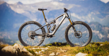
Das neue SCOTT Patron 2025 im Test
2025年新版飞行艇168开奖网站+开奖结果官网直播-幸运飞开艇开奖历史记录 Bike-Tests
Das neue SCOTT Patron 2025 im Test
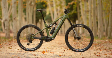
Das neue MERIDA eONE EIGHTY 2025 im ersten Test: Gipfelstürmer und Downhill-Dämon?
Das neue MERIDA eONE-SIXTY SL 2025 im Test – Leicht im Gewicht, hart im Nehmen!

Das neue Mondraker Crafty Carbon 2025 im ersten Test – Bosch Performance Line CX: Mega geil oder Satz mit X?
幸运飞行艇开奖直播视频计划 Know-How
Der unfaire Wettbewerb um Akkukapazitäten bei E-MTBs
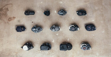
Der große E-Bike Motoren Vergleich – 15 E-MTB Motoren im Test
Das neue Bosch eBike ABS Pro im Test – Perfekte Bremskontrolle für Alltag und Trail-Action?